Raspberry Pi 3 + Official 7-inch Touchscreen Photo Frame with Ambient Light Sensor Auto-Brightness (BH1750FVI + I2C + Python)
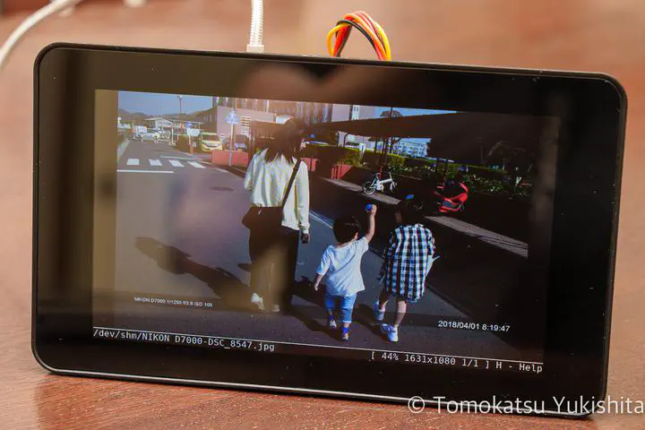 Image credit: Tomokatsu Yukishita
After building a cloud-connected photo frame with Raspberry Pi 4, I had a spare Raspberry Pi 3 and official 7-inch touchscreen sitting around. I turned them into another photo frame — and added a GY-30 BH1750FVI ambient light sensor to automatically adjust display brightness based on the room’s lighting.
Hardware
Raspberry Pi 3

Official 7-inch Touchscreen
800×480px, 24-bit RGB color, 60 fps, up to 10-point multitouch.

Case for the Official Touchscreen
Designed to house both the Raspberry Pi 3 Model B and the 7-inch display.

Connecting the Display
Follow the Raspberry Pi Touch Display official documentation to assemble the display.
Display Rotation Setting
By default the display is rotated 180°. The fix depends on your OS version.
The lcd_rotate=2 option below is for Raspberry Pi OS Bullseye and earlier (legacy/FKMS mode). On Bookworm (2023 and later), lcd_rotate is not officially recommended — use the Screen Configuration GUI tool instead.
The config file path also differs by OS version:
- Bullseye and earlier:
/boot/config.txt - Bookworm and later:
/boot/firmware/config.txt
For Bullseye and earlier (legacy/FKMS mode):
sudo vi /boot/config.txt
Add the following line:
lcd_rotate=2
Slideshow Program
The slideshow uses the Python script from the cloud-connected photo frame project (photoView4).
Display Brightness Control
Running the display at full brightness all the time is uncomfortable in a dark room. The official 7-inch display allows brightness control by writing a value (0–255) to a sysfs file:
echo "100" | sudo tee /sys/class/backlight/rpi_backlight/brightness
Adding an Ambient Light Sensor (BH1750FVI)
Rather than setting brightness manually, I wanted it to adjust automatically based on ambient light.
Parts
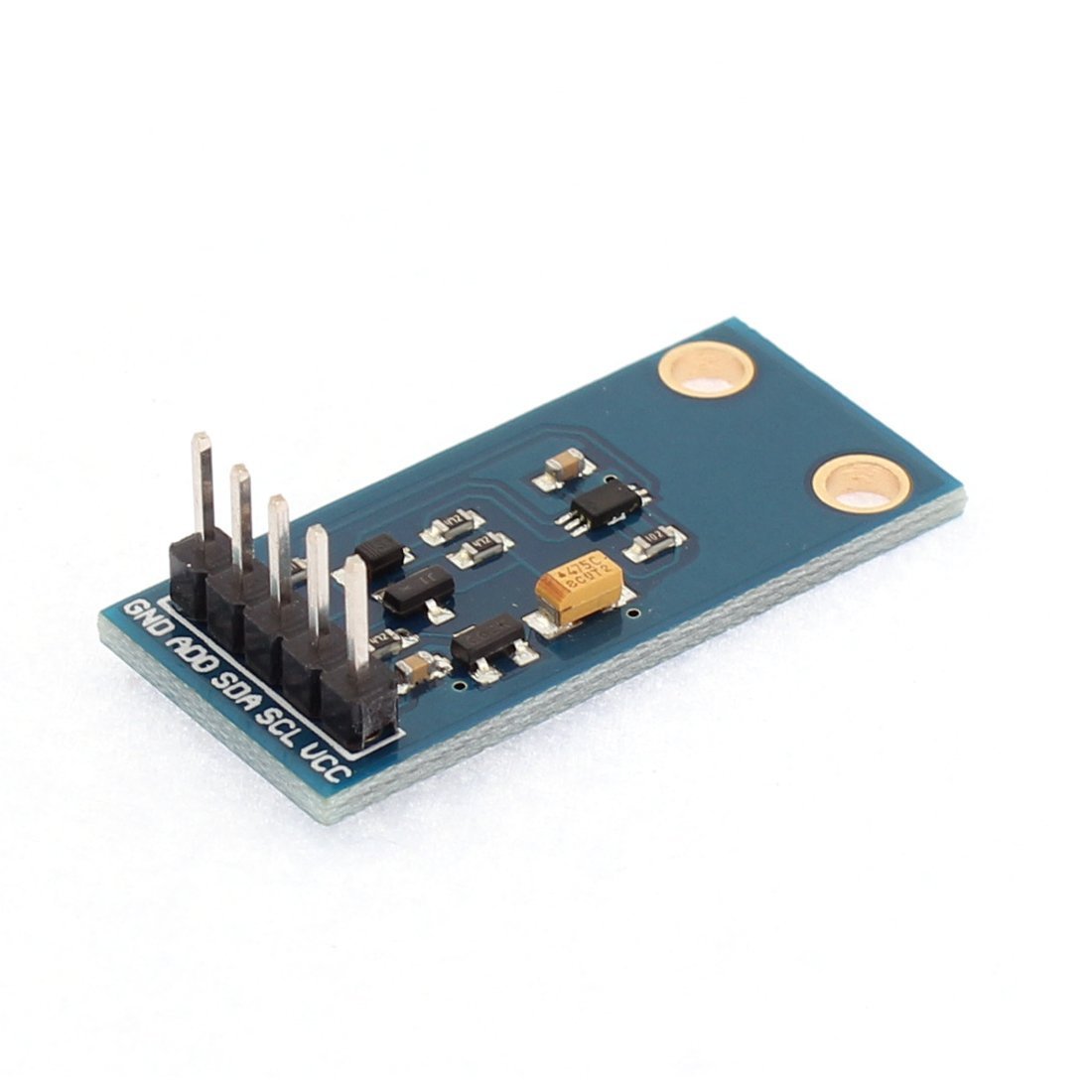

Connecting to Raspberry Pi via I2C
The BH1750FVI communicates over I2C. Refer to the Raspberry Pi GPIO pin layout for wiring.
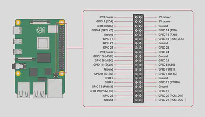
Wiring Table
| Raspberry Pi | GPIO Pin | BH1750FVI |
|---|---|---|
| GPIO2 (SDA) | 3 | SDA |
| GPIO3 (SCL) | 5 | SCL |
| 5V Power | 2 | VCC |
| Ground | 14 | ADO |
| Ground | 20 | GND |
Verifying the Sensor (Python)
After wiring, confirm data is coming through. Based on a reference implementation on GitHub:
#!/usr/bin/python3

import smbus

Bus = smbus.SMBus(1)
Addr = 0x23
LxRead = Bus.read_i2c_block_data(Addr, 0x11)
print("Illuminance: " + str(LxRead[1] * 10) + " lx")
LxRead2 = Bus.read_i2c_block_data(Addr, 0x10)
print("Brightness: " + str((LxRead2[0] * 256 + LxRead2[1]) / 1.2))
Running it confirms the sensor is working:
root@raspi3-photo:~# python br.py
Illuminance: 1650 lx
Brightness: 990.8333333333334
Auto-brightness Control Program
The final program adjusts backlight brightness smoothly based on ambient light readings:
- Target brightness levels are defined per illuminance range
- The display brightness is incremented or decremented one step at a time toward the target
- The I2C sensor is polled every 300ms — polling faster than this results in incorrect readings with SMBus
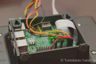
Sensor Placement
The sensor is mounted on the protruding back section of the case, where it receives ambient light from the room.

Source Code
The complete program (object-oriented version) is on GitHub:
Demonstration
The brightness adjusts smoothly as ambient light changes:
Summary
| Component | Role |
|---|---|
| Raspberry Pi 3 | Main computer |
| Official 7-inch Touchscreen | Photo frame display (800×480px) |
| GY-30 BH1750FVI | I2C ambient light sensor |
| Python (smbus) | I2C communication and brightness control logic |
Adding the light sensor makes the photo frame genuinely pleasant to use — bright during the day, dimmed at night, automatically.
Tomokatsu Yukishita (雪下 智且)
Engineering Manager / Real Estate Transaction Agent
Engineering manager connecting embedded development with cloud and AI. I apply quality standards from mission-critical systems to modern product and development workflows.