Raspberry Pi 3 + 公式7インチタッチスクリーンでフォトフレーム制作
 Image credit: Tomokatsu Yukishita
はじめに
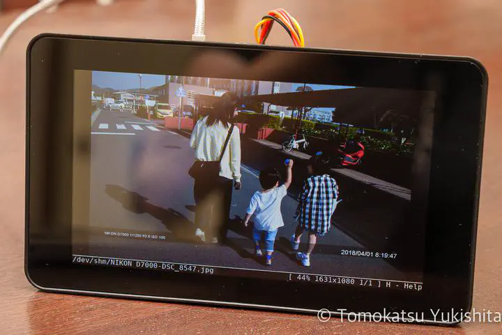
以前、Raspberry Pi でフォトフレームを作りました。 今回は Raspberry Pi 3 と 7インチタッチスクリーンが余っていたので、こちらでもフォトフレームを作ってみようと思います。
用意するもの
Raspberry Pi 3
Raspberry Pi 3 Model B シングルボードコンピュータ
公式タッチスクリーン
Raspberry Pi 公式 7" タッチスクリーン LCD Element14
公式タッチスクリーン用ケース
Raspberry Pi & 7インチ LCDタッチスクリーン 拡張ボードケース ABS樹脂 (RSコンポーネンツ製) (黒)
ディスプレイの接続
公式のマニュアルを参考にして組み立てます。
Raspberry Pi Touch Display
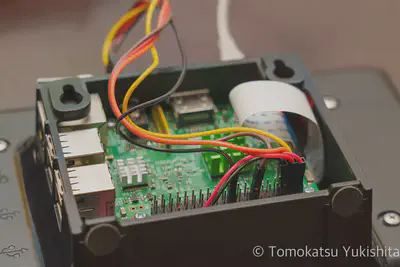
リボンケーブルと電源をGPIOに接続します。
The following image shows how to attach the Raspberry Pi to the back of the Touch Display (if required), and how to connect both the data (ribbon cable) and power (red/black wires) from the Raspberry Pi to the display. If you are not attaching the Raspberry Pi to the back of the display, take extra care when attaching the ribbon cable to ensure it is the correct way round. The black and red power wires should be attached to the GND and 5v pins respectively.
(Google翻訳)
次の画像は、Raspberry Piを背面ディスプレイに接続する方法(必要な場合)と、データ(リボンケーブル)と電源(赤/黒のワイヤー)の両方をRaspberryPiに接続する方法を示しています。 Raspberry Piをディスプレイの背面に取り付けていない場合は、リボンケーブルを取り付けるときに特に注意して、正しい方向に配線されていることを確認してください。黒と赤の電源線は、それぞれGNDピンと5vピンに接続する必要があります。
引用元 : https://www.raspberrypi.com/documentation/accessories/display.html
公式ディスプレイ用の設定変更
標準だと180度反転してしまっているので、これも公式のドキュメントを参考にして反転させます。
KMS/FKMSモードとレガシーモードの2通りあるようなので注意してください。 RaspberryPi4 だと KMSモードがデフォルトだそうです。
pi@raspi3-photo:~ $ sudo vi /boot/config.txt
lcd_rotate=2
スライドショー用のPythonプログラム
これは以前製作した自作Pythonスクリプトを使います。
そのままだと眩しい
ここまで実施すればフォトフレームの出来上がり・・・なのですが、なにぶん画面が眩しい。 ここは輝度調整したいところです。
公式7インチディスプレイの輝度変更方法
公式7インチディスプレイの輝度変更方法は以下のようにすれば良いです。
root@raspi3-photo:~# echo "100" | sudo tee /sys/class/backlight/rpi_backlight/brightness
/sys/class/backlight/rpi_backlight/brightness に値を書き込んでやれば輝度変更ができます。
環境光に応じてディスプレイの輝度を変えたい
輝度変更できるようになったら、環境光に応じてディスプレイの輝度を変えたくなります。
ELEGOO 120pcs多色デュポンワイヤー、arduino用ワイヤ—ゲ—ジ28AWG オス-メス オス-オス メス –メス ブレッドボードジャンパーワイヤー
WINGONEER GY-30 BH1750FVIデジタル光強度センサモジュールI2Cラズベリーパイ
ということで購入したのが GY-30 BH1750FVI 光センサーです。 一緒にジャンパーワイヤーも購入しました。
Raspberry Pi と SPI 接続
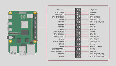
購入した GY-30 BH1750FVI 光センサーを Raspberry Pi と SPI 接続します。 公式ドキュメントを参考に接続します。
SPI hardware
GPIO and the 40-pin header

接続対応表
| RaspberryPi | Raspberry Pi PIN番号 | GY-30 BH1750FV |
|---|---|---|
| GPIO2 (SDA) | 3 | SDA |
| GPIO3 (SCL) | 5 | SCL |
| 5V Power | 2 | VCC |
| Ground | 14 | ADO |
| Ground | 20 | GND |

光センサー(SPI)のデータ読み出し
接続した光センサーが動作するか動作確認してみます。 Pythonで書いてみます。
#!/usr/bin/python3

import smbus

Bus = smbus.SMBus(1)
Addr = 0x23
LxRead = Bus.read_i2c_block_data(Addr,0x11)
print("照度: "+str(LxRead[1]* 10)+" ルクス")
LxRead2 = Bus.read_i2c_block_data(Addr,0x10)
print("輝度: " + str((LxRead2[0] * 256 + LxRead2[1]) / 1.2))
上記プログラムは Opensourcetechブログ さんを参考にさせていただきました。
RaspberryPi/bh1750fvi.py at master · kujiraitakahiro/RaspberryPi
GitHubにも公開されています。
早速実行すると輝度が取得できました。
root@raspi3-photo:~# python br.py
照度: 1650 ルクス
輝度: 990.8333333333334
周囲の明るさに応じてディスプレイ輝度を自動調整する
ここまで来たら、取得した明るさに応じてディスプレイ輝度を自動調整するプログラムを作ります。 輝度調整は滑らかにしたかったので、10ms周期で動く Python プログラムを作りました。
仕組みは簡単で、明るさごとにターゲットのディスプレイ輝度を定義して、取得した明るさに応じてディスプレイ輝度を1ずつインクリメント/デクリメントする、というものになっています。
SPIは早すぎると取得できない
前述の SMBus を使用したSPI通信を行いますが、ループ速度が早すぎると正しく値を取得することができません。 ですので、300ms周期で取得するようにしました。
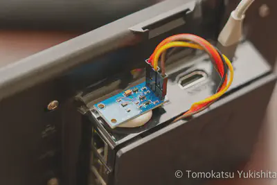
GY-30 BH1750FVI 光センサーの設置
設置箇所は背面の出っぱったところに設置しました。 当然ですが光が当たるところに設置した方が良いかと思います。

作成したプログラム
作成したプログラムは GitHub に公開しています。
2022/5/25 オブジェクト指向で作り直しました。
GitHub - yukishita/lcdBrightness2: GY-30 BH1750FVI 光センサー で明るさを取得して Raspberry Pi 公式7インチタッチスクリーンの輝度を調整するプログラム(オブジェクト指向版)
デモンストレーション
作成したプログラムのデモ動画です。
まとめ
Raspberry Pi 3 + 公式7インチタッチスクリーンにGY-30 BH1750FVI 光センサーを追加して輝度変更対応のフォトフレームを作ることができました。
課題
特になし


